![]()
|
|
Moving Coil Step-Up Transformer Design Considerations
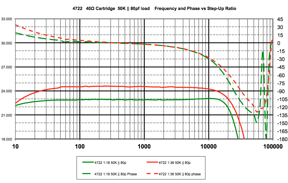
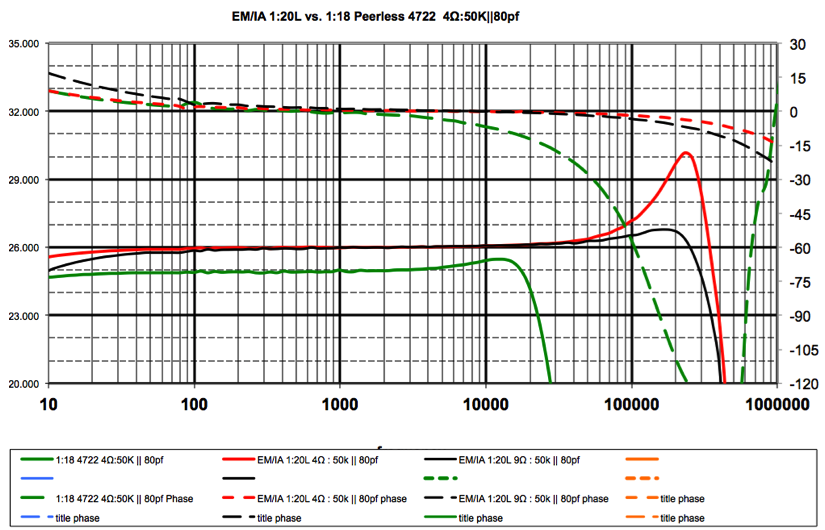
One of the most enlightening texts about transformer design is “Transformers for Electronic Circuits” by Nathaniel Grossner. In this book he acknowledges all of the prior work done on this subject. Then he breaks the design process down to the analysis of what theory says and synthesis, or what actually happens in practice. This approach tends to uncover details and relationships that a less exhaustive procedure misses and is what inspired my Theory vs. Practice approach outlined below. History The origins of using transformers for stepping up the voltage of a moving coil (MC) cartridge trace back to microphone step-up transformers (SUT). These transformers were used to step up the low voltage from a typical ~50Ω microphone to a 50KΩ input of a microphone preamp. When you step back and look at mating a Denon 103 (40Ω) to a moving magnet (47KΩ) phono stage, one can see the chance for a perfect fit. Vintage microphone transformers were inexpensive and plentiful on the surplus market so they were a low risk proposition to try. This led to widespread use, and many cartridge manufacturers offering dedicated transformers to match their cartridges. One microphone transformer that found widespread use as a SUT is the Peerless 4722, which was used in the Altec 1567A mixer. Below are the frequency and phase plots of the 4722 when wired for both 1:18 and 1:36, assuming a Denon 103 and a typical MM phono input.
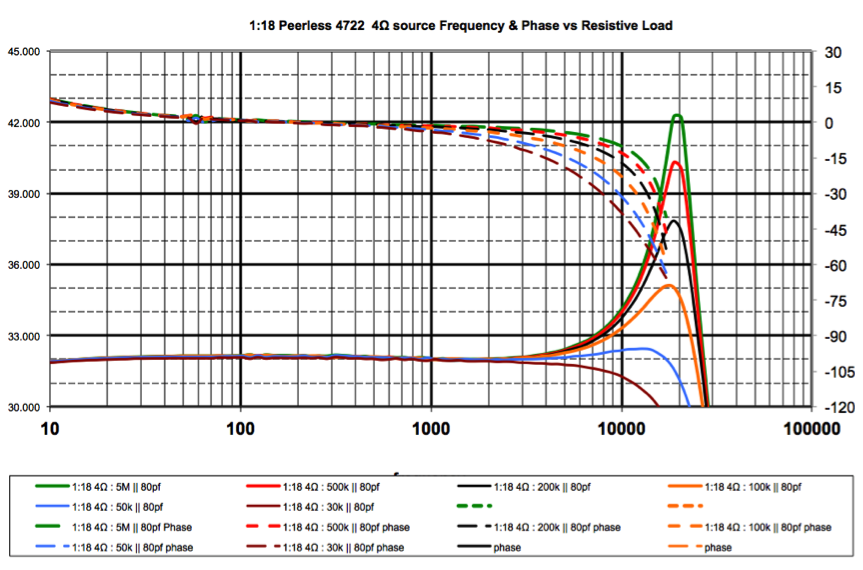
Note: All measurements were taken at low signal levels with a 10X probe to minimize capacitance. This results in a reduced noise floor that explains the slight mid-band ripple in response. These are measurement artifacts and do not represent the actual transformer behavior. The 4722 has a tapped primary which allows for it to be used to match either a 38Ω or a 150Ω source to a 50kΩ load. This translates to a 1:18 or 1:36 voltage step-up ratio. Looking at the two plots we see different behavior in the frequency and phase domain. The reduced inductance from using one half the primary results in more drastic roll-off at low frequencies for the 1:36 connection. This lack of inductance in relation to the driving source impedance also shows up as increased phase shift at 10Hz. The combination of other more complex transformer behavior causes differences at the top end of the spectrum. The transformer load often hides these anomalies, and the high frequency phase behavior is often a good indication of the complex interactions at hand. This erratic behavior can be problematic if it occurs at the top of the audio band but becomes less of an issue the further past 20kHz it is pushed. Everybody wants a universal one-size-fits-all solution to this problem, and the revered 4277 mates nicely with the 40Ω Denon103 into a MM phono stage. This combo does not represent the ultimate in measured performance. It gave a pleasing sound. As a nearly free found object, one could do much worse. It isn’t surprising that this type of transformer found enough use as a SUT to create demand and drive the prices up; causing several manufacturers to create dedicated transformers for MC cartridges. It is interesting what happens when we start to look at the results of varying the parameters that dictate transformer frequency and phase behavior. The 4722 is a well known device which if properly implemented gives a classic vintage tone allowing it to serve as a good starting point for exploring this topic. Theory Basic transformer theory states that frequency and phase behavior is controlled by the driving source and load characteristics. The driving source is the internal impedance of the cartridge and is typically in the 1-40Ω range for MC cartridges. The load is the combination of resistive and capacitive elements across the transformer secondary. This load is traditionally assumed to be a 47kΩ input resistor in parallel with the input capacitance of the phono preamplifier along with any interconnect cable capacitance. The following graphs show how each of these parameters affects the behavior of a SUT. In the following examples the 4722 is wired for 150Ω:50kΩ impedance ratio which represents a 1:18 voltage ratio. For each individual parameter graphed, the other two parameters are minimized to best show the general pattern of behavior. For example, in the case where capacitance is being varied, the cartridge impedance is set to 4Ω and load is set at 500kΩ to better isolate the capacitive effect. Resistive LoadingWhen using an external SUT, it is plugged into the MM input of a phono preamplifier the resistive part of the load is almost universally 47kΩ. This 47kΩ load is there for the benefit of a moving magnet cartridge and has no fixed benefit for the MC/ SUT combination.
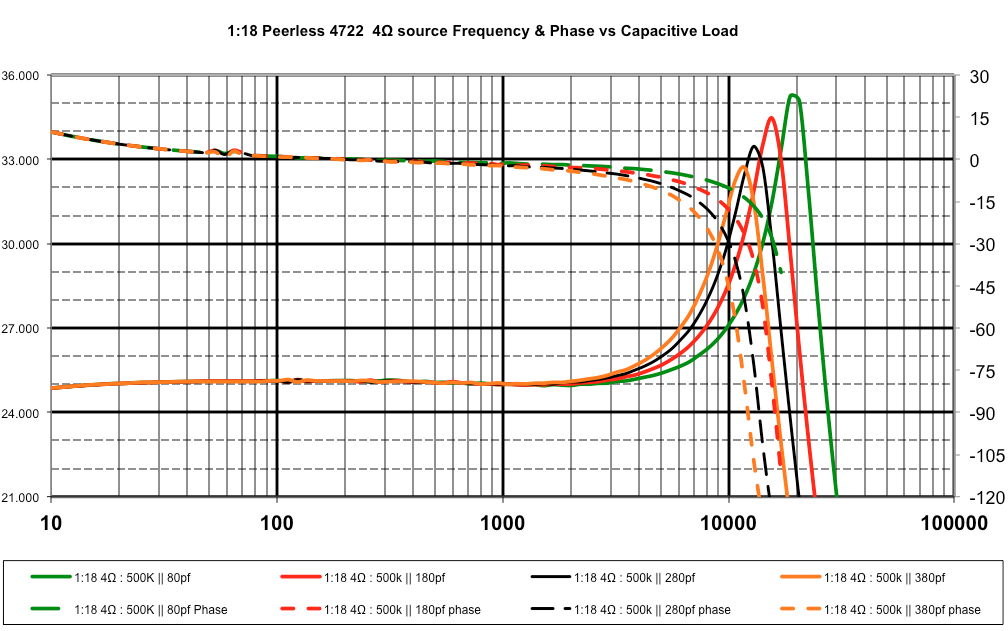
The above plots use a 4Ω source to simulate a low impedance cartridge like an Ortofon SPU. The 80pf of capacitance is a very low number and represents the minimum amount possible in practice. Assuming 80pf, the green plot shows a 5MegΩ load and the net result is a 10dB resonant peak at 20kHz with a phase shift of 7.5° @ 10kHz. This is what is called an under-damped response and the traditional solution is to increase the load (lower the load resistance) to reduce this peak. As the load approaches the 50kΩ that the transformer was designed to be terminated, you see the peak disappear, but you also see the phase shift @ 10kHz quadruple to 30°. This is called a critically damped response. Going lower in value to 30kΩ shows attenuation within the audio band and further phase shift at 10kHz, which is representative of an over-damped response. The low frequency amplitude and phase characteristics stay largely unchanged since they are controlled by the relationship of the cartridge impedance to the transformer primary inductance. As seen in the first plot, resistive loading will also affect the overall gain at the output of the transformer. All of the remaining graphs have been normalized @ 1kHz for ease of comparison. Capacitive LoadingIn addition to the load resistance, some amount of input and cable capacitance appears across the output of the transformer. With MM cartridges this capacitance is required to tame a rising top end. For the MC-SUT combo, capacitance is simply a liability and should be kept as low as possible.
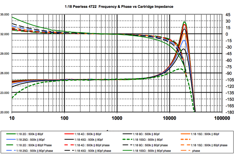
The same 4Ω cartridge is shown above keeping the resistive load at 500kΩ. It can be seen that as the capacitance increases from 80pf, the resonant peak gets lower in magnitude and in frequency. In this case it is important to note that increasing the capacitive load drives the peak well into the audio band. As with resistive loading, capacitive loading has little effect on the low frequency behavior and a pronounced effect on the high frequency phase behavior. Driving Impedance The final part of this equation is the role the cartridge impedance plays. At first glance, increasing the cartridge internal impedance seems to have a similar effect to increasing the load on the secondary. As cartridge impedance increases, it works to damp any high frequency ringing. Looking a bit more closely it becomes clear that unlike the case with secondary loading, the high frequency phase shift is less pronounced. As the cartridge impedance is increased, the effect of a fixed primary inductance shows up as low frequency roll-off and its associated phase shift.
The above three graphs show that for an existing transformer design there are a number of ways to achieve similar results, but none of them address the underlying problem of trying to shoehorn an off the shelf device into an existing circuit. The 4722 and its microphone transformer brethren all show a similar pattern of behavior that is mostly hidden by the 47K input impedance of a phono stage. The magnitude of the peak may be a few decibels larger or smaller, and the frequency may be an octave higher, but the pattern is generally the same. In some cases the 47K is not enough of a load to tame the response, so additional loading or an additional R/C network (Zobel) is used. This is accepted engineering, but the perceived results do not always follow what engineering dictates to be correct. This leads to the belief that SUT selection is some sort of black art. A few key takeaways from the theory are:-The 47KΩ input resistance of a phono stage is an artifact from a different system. -Resistive loading can damp a peaking response at the cost of phase shift. -Capacitive loading lowers the resonance in frequency and causes increased phase shift. -Increasing source impedance can also damp a peaking response at the cost of low-end extension. -Turns ratio is for gain, not impedance matching -Erratic high frequency behavior is inherent to all transformers. The further above the audio band they can be pushed, the better. PracticeTo take this “black art” deeper into the quagmire, we only have to consider the load the cartridge wants to see and then try to relate that into the variables at play. Unfortunately the “optimal load” for any cartridge is a hotly contested very subjective topic; there are no hard fast rules. The math for calculating the reflected load is well known and the transformer simply reflects back the phono stage input impedance divided by the turns ratio squared. To keep the math simple assume a 1:10 voltage ratio transformer will reflect back a 100:1 impedance ratio so 47kΩ will appear to the cartridge as 470Ω. What happens if we want our cartridge to see a 1kΩ load? One approach would be to go to a lower turns ratio SUT and a 1:7 would solve the problem since 47,000Ω/49=959Ω which is close enough to 1000Ω for this purpose. A better option would be to simply increase that 47kΩ input value to 100kΩ, which assuming a 1:10 reflects back 1000Ω. Remember that 47kΩ value is a remnant from another cartridge type and is not required for use with a SUT. While some use it as an asset to damp a peaking response near the top of the audio band, 47kΩ is actually a liability that simply makes an inferior device appear to behave. If the 47kΩ value is changed to the 300kΩ value used in the EM/IA LR Phono Corrector, the reflected load from that 1:10 suddenly becomes 3kΩ. If a lower value is required, additional resistance should be added in parallel with the primary to load the cartridge directly. With SUT’s there will always be some value that represents the minimum load obtainable. While a larger value load than 47K is not required for many SUT’s to operate in an acceptable manner, it does allow for a wider range of loading options should they be needed. Taking a step back, knowing that a properly designed SUT can work into a lightly loaded input, a transformer can be designed to match a given cartridge impedance to that light load (A light load has a high resistive value). Armed with this knowledge, the resonance and any top end anomalies can be pushed out of the audio spectrum by a factor of 5-10 or more! The situation pictured below represents a best-case scenario for a 4Ω cartridge using the 4722 compared to an EM/IA 1:20L that is intended for carts in the 4-9Ω range. It should be noted at this point that the EM/IA SUT designations state the turns ratio set to the required gain and a general designation for the range of cartridge impedance the SUT is suitable for. When a SUT is ordered, a general discussion is had about the cartridge and phono stage it will sit between. The transformer will be designed specifically for that case, and an impedance designation (SL, L, M, H) is given for future reference. Inevitably people change cartridges and need to change SUT’s and a generic designation for a range allows for us to help you rehome your current unit should you need to move into a new one.
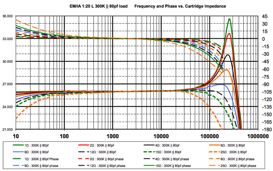
At first glance the ~4dB peak when driven from 4Ω seems a bit alarming but upon realizing that this peak occurs above 200kHz: a full decade above the audio band, this alarm quickly fades to black. The next thing that becomes apparent is the slight amount of low frequency attenuation at 10hz for the 9Ω cartridge. This is a conscious design decision and simply represents a choice based on sonic performance. It has often been said that a transformer can be designed to give 12 octaves of bandwidth; so choose them wisely. When considering phono playback, nothing of value exists below 20hz. Taking advantage of a transformer as a high pass filter provides a gradual first line of defense against unwanted low frequency system pickup. As an added plus for trimming an octave from the bottom, an extra three can be added to the top. In the case of the 1:20 L, 14+ octaves of bandwidth are realized. Looking a bit more closely at the 1:20 L design, a clear picture of the relationships at hand can be seen. The interactions involved are that of a system consisting of the cartridge, SUT and phono stage. The load was chosen to match that of the EM/IA LR phono corrector coupled to the SUT with a low capacitance shielded interconnect. Drive impedances of 1Ω to 25Ω were swept to show the overall range of behavior.
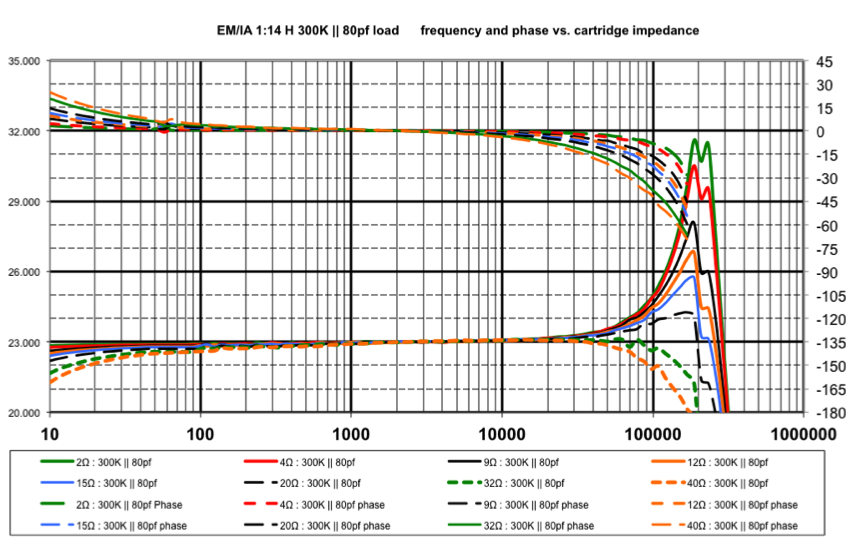
If you were to feed this combo with a 2Ω source like an Audio Note IO Ltd (1Ω cartridge + 1Ω tonearm), a nearly 10dB peak @ 250kHz pops up with bass extension well into the realm of tonearm resonance and record warps. The 10dB peak isn’t too concerning since it is more than a decade above the audio band and the low end extension needs to be addressed on a system to system basis. Taking it to the other extreme and using a 32Ω Allaerts MC2 Finish, both the top and bottom response are compromised. As always, the truth lies in the middle. With this transformer, cartridges in the 2Ω-9Ω range give both acceptable measured results and great sonic results. Going higher than 9Ω starts to lose some bass authority and sonically creeps toward the vintage sound of microphone transformers. These are not hard and fast rules, just observation of a pattern of behavior gleaned from designing and listening to hundreds of different cartridge and SUT combinations over the past few decades. Now Let's consider the cartridge in question is something along the lines of a 34Ω VDH Colibri, then one can simply slide into a 1:14 H where all of the parameters are adjusted to better deal with the higher cartridge impedance.
The 1:14H plots have the same family feel as the 1:20L but now carts in the 15Ω-40Ω range have plots similar to what the 4Ω-9Ω have with the 1:20L. When moving to the higher impedance cartridges, capacitance and reflected load quickly become problematic so the maximum ratio must be carefully considered. A transformer simply transforms impedance and assuming a 1:20 voltage ratio, a 1:400 impedance ratio is realized. A 35Ω cartridge feeding a 1:20 appears as a14,000Ω source impedance that has to drive the downstream load. Suddenly the traditional 47kΩ load and a hundred picofarads of capacitance can have a substantial impact on the overall behavior. 200pf of capacitance has an impedance of 14kΩ @ 57kHz. While some consider -3dB @ 57kHz a win… I do not. Dropping the turns ratio to 1:14 cuts that 14kΩ number in half to just under 7kΩ and extends the top end by an octave.
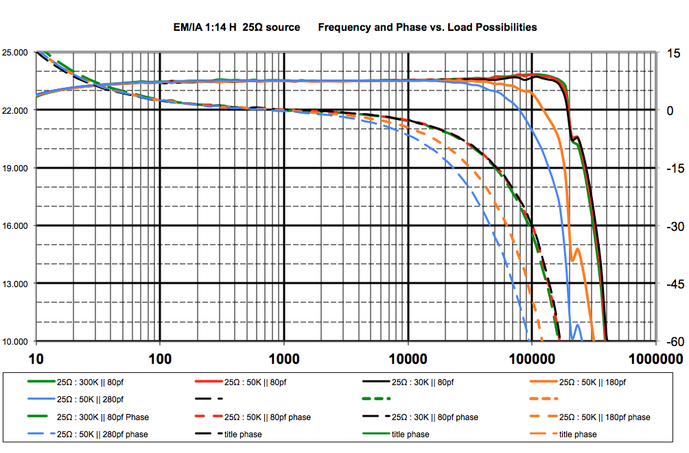
In the event that your phono input is fixed at 47kΩ, there is no need to worry. The plots above represent various loading options for the EM/IA 1:14 H. Unlike the 4722, the 1:14 H shows minimal change for resistive loads from 300kΩ to 30kΩ in both the frequency and phase domain. What does change appreciably is the maximum value load possible in each case. For the 300kΩ case the reflected load is 1530Ω and for the 47kΩ case the reflected load is 1/6th that value at 230Ω. What does become clear from these plots is what capacitive loading does to both the frequency and phase. This is why great care must be taken to keep capacitance to a minimum. Turns RatioThe sole purpose for the selection of a turns ratio is to address system gain structure. Having too little step-up results in a weak. dynamically compressed sound. Having too much step-up runs the risk of high frequency dynamic overload of the phono preamplifier. A fatal flaw of the accepted SUT selection process has one choosing the turns ratio to reflect back some arbitrary load printed in a cartridge’s specification sheet. If the load is to be increased, additional resistance is placed across the secondary to reflect back a lower value. (A heavier load has a lower resistive value) It can clearly be seen in the 4722 plots that lowering the terminating resistor value on the secondary impacts both the high frequency amplitude and phase behavior. This can cause an audible difference to the transformers sonic signature that is often mistakenly attributed to the sonic difference due to the change in cartridge load. A key understanding is that while the step-up ratio and the load are connected, they must be considered independent of each other. In simple terms, the step-up ratio should be chosen to match the gain of the cartridge to the input of the phono preamplifier. A low outpu,t low impedance cartridge like the Benz Micro Ebony TR which has a 0.1mV output with, 1Ω internal impedance can benefit with a 1:50 step-up ratio. Moving the other direction, the My Sonic Lab Signature has a 0.5mV output with an impedance of 1.4Ω, and is therefore better suited for a lower ratio. It must be noted that pairing a high output cartridge with a high ratio transformer has a good chance of dynamically overloading the phono input at high frequency. The general trend for many transformer designs is to offer multiple connection possibilities to allow multiple ratios to mate with a wide range of cartridges. This Swiss Army knife approach is appealing at first but ultimately leads to a compromised design. The best results come from simply choosing the right tool for the job. Core MaterialI find it necessary to leave the realm of the technical to discuss this topic. For me the choice is simple. For the extremely low flux levels found in a SUT, 80% nickel is king. People will tout modern materials like amorphous and nanocrystalline and cite technical data to justify their superiority. I have used these materials, and my ears tell me that they have nowhere near the ability of 80% nickel to dig the emotion of the music out of the groove. Conclusion Different cartridges from the same manufacturer all seem to have a “House Sound”. Koetsus are a completely different animal than Lyras, and each has their devout followers. Neither is correct, neither is wrong… they are just different. Ultimately your ears will tell you the flavor you like, and let you enjoy the taste of your music. The same holds true for SUT’s. We have spent considerable time designing, listening to, and measuring audio gear; and that is what creates our “house sound”. Remember that our approach is to design and listen first; then we measure to try to find a correlation to what we hear so progress can be made. For a SUT, creating a design that takes into account the cartridge that will be driving it and the load it will be seeing allows for a device that can jump through all of the engineering hoops while still adhering to the underlying goal of musical truth.
|
|