![]()
|
|
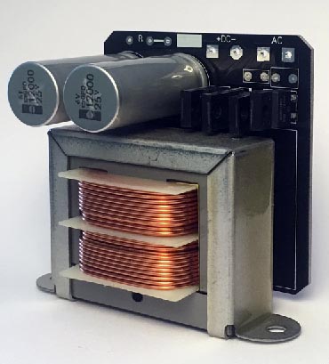
Filament Modules
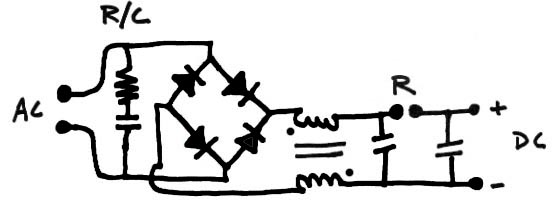
The origin ofthese modules was the need for a compact easy to mount power solution to feed Coleman Regs. The center point of the design is a balanced choke input filter using a schottky bridge for rectification. The basic schematic is pictured below and the key point here is the choke is operating in differential mode with only the leakage inductance helping for common mode noise rejection.
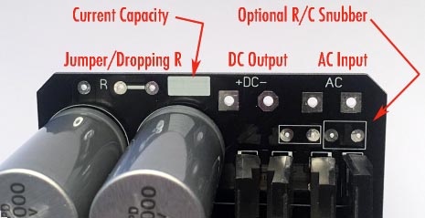
The position marked R is to either be filled with a jumper to parallel the capacitors or with a resistor to make it a LCRC filter. A resistor in this position can also be used to trim the output voltage to a specific value. The modules also have positons for adding a R/C snubber to the input to help suppress noise. They are available in vewrsions with either a 2 amp or 3.5amp maximum current and can provide up to a 15VDC output.
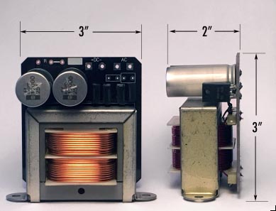
The modules are self-contained and mount with two screw holes. They have a 3" X 3" X 2" footprint.
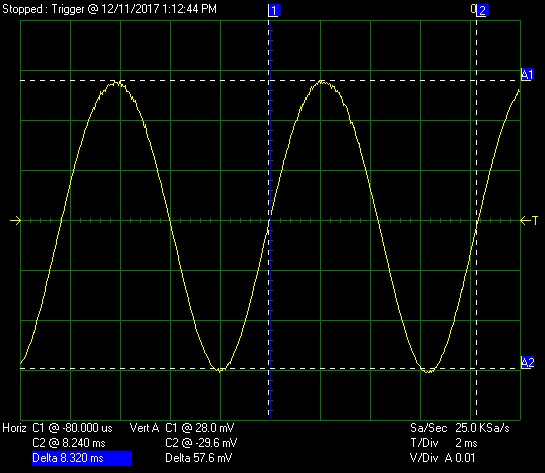
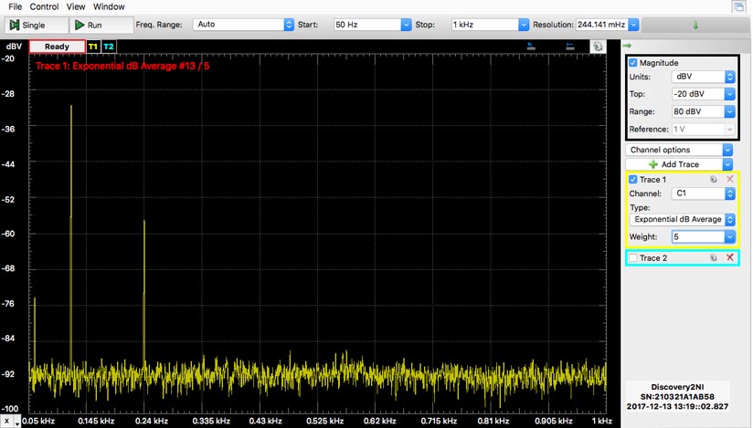
Due to the nature of choke input filtration the output waveform is nearly a pure 120hz sinewave with very low harmonic content. The image below is of a module delivering 3A of current resulting in 58mv p-p ripple.
|
|